Strata-Teck- Lock Rock Injected
HMI- 402 Deep Injection
Polyurethane Foam Injected
MACHINERYPADSTABILIZATION
MACHINERY PAD STABILIZATION
The Problem
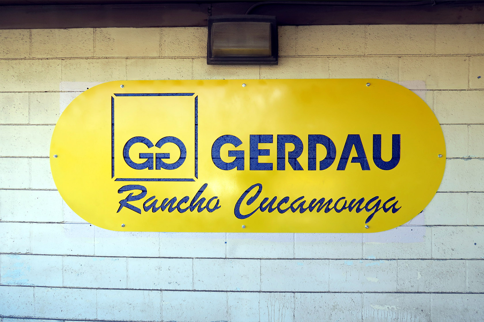
Gerdau North America, is one of the leading producers of rebar in the United States. Their product reinforces the concrete in bridges, buildings, skyscrapers, homes, warehouses, foundations, and roads — the structural backbone of modern construction. With building demand booming, their product is in high demand and their production line cannot afford to stop.
At one of Gerdau’s foundries, an integral piece of machinery was settling due to a combination of poor soil conditions, constant vibration, and the extreme weight of the equipment itself. The NKK rebar shear — the only machine of its kind operating at the facility — weighed an estimated 70 tons with its concrete and steel pedestal. If this machine went offline for any reason, production stopped until it was fixed.
The trouble traced back forty years. When the machine was originally placed in operation, no effort had been made to compact the loamy sand and gravel mix beneath the machinery pedestal. Four decades of vibration, weight, and use had caught up with the foundation.
The Previous Repair That Didn’t Hold
A previous repair attempt in 2004 required complete disassembly of the machine and its removal — using a 100-ton crane and a large contingent of workers — to modify the foundation base and stop the settlement. As part of that work, the 14-foot by 8-foot concrete base was wrapped in one-inch steel plate, adding significant additional weight to the already 70-ton shear and pedestal.
But no one addressed the underlying problem: the loose soil beneath the pedestal. Nothing was done to stabilize or modify the subsurface conditions. As a result, the same settlement problem returned almost immediately after the expensive repair was completed.
Understanding the Site: Why This Soil Fails
The Gerdau foundry sits in Fontana, California — on a large alluvial fan formed over thousands of years by creek cobble, sand, and loam washing down from the San Gabriel Mountain range. The surface layer transitions from Vista Decomposed Granite (commonly called “DG”) to Hanford Sandy Loam below. Both soils are known in the geotechnical community for two problematic behaviors: downhill creep and settlement.
Here’s why that matters for heavy machinery:
- The soil is porous. Decomposed granite and sandy loam both allow water to migrate freely through the subsurface — especially during the torrential rain events common to Southern California’s winter storm cycles.
- Water moves the soil. As water flows through the profile, it carries fine particles away, leaving voids between the medium and large cobble. Over time, those voids collapse under load, causing settlement.
- The soil moves on its own. Alluvial fan deposits naturally creep downhill over time due to gravity and repeated wet-dry cycles. It’s slow, but it’s constant.
- Vibration accelerates everything. Heavy industrial equipment doesn’t sit passively on top of soil — it actively works against it. Every cycle of a 70-ton rebar shear sends vibration energy into the ground, reorganizing loose particles and compacting them unevenly beneath the pedestal.
And in this case, the vibration wasn’t incidental — it was violent.
Every time the NKK shear cut through a bundle of rebar, it simultaneously sliced through 100 pieces of steel. The resulting shock waves shook the pedestal and the ground beneath it, driving additional settlement and disturbing the already unstable soil profile with every cycle of operation.
The Symptoms Gerdau Was Experiencing
Each of those soil behaviors was showing up in the day-to-day performance of the machine:
- Progressive settlement — the machine was slowly sinking into the ground, even with the 2004 repair reinforcements in place. Soil compaction beneath the pedestal couldn’t keep up with the load above it.
- Uneven settlement — the pedestal wasn’t settling uniformly, which creates stress on the machine’s internal components and risks misalignment.
- Voids forming beneath the concrete base — water migration was washing fines out from under the pedestal, creating empty pockets that eventually collapsed and dropped the machine further.
- Recurring failure despite expensive intervention — because the 2004 repair only reinforced the machine’s foundation (steel plate, added weight), without addressing the soil beneath it, the underlying cause was untouched. The repair was, in effect, putting a heavier load on the same failing ground.
The Root Cause
All of this points back to one thing: the soil itself. The problem was never the machinery, the pedestal, or the concrete base. Those were symptoms. The root cause was the Vista DG and Hanford Sandy Loam beneath the structure — soil that erodes with every rain, shifts with gravity, and loses density under the constant vibration of a 70-ton shear working above it.
Fix the machine and ignore the soil, and the machine will keep sinking.
Fix the soil, and the machine stays where it belongs.
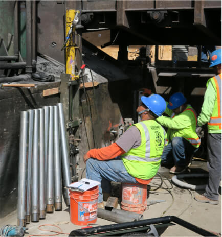
Initial investigation of the site we perform with a detailed machinery plan set in hand. During the shear operation inspection, mild vibration was experienced from the rebar conveyor as far out as twenty feet from the shear. The shear cuts hot stamped rebar into correct lengths immediately after each piece exits from the stamp mill, twenty pieces at a time. There was an additional vibration felt at each cut, increased by the loose sand and gravel soil beneath the shears pedestal. This caused undue stress and misalignment on the conveyor attachments. Multiply adjustments and costly modifications have we perform over the past thirteen years to no avail.
Foundation Technology was contracted to provide a permanent solution that would keep the foundries only shear in operation.
Addressing Problem #1: Structural Support With Push Piers
Foundation Tech determined that ECP PPB-400 push piers with PPB-350-IP inertia sleeves would be the most economical way to lift and permanently support the machine pedestal — without disassembling the shear as the 2004 repair had required.
But sizing the pier system required more than just calculating the static weight of the pedestal. A typical foundation repair uses a safety load factor of 2 to 2.5 times the static weight. That standard is adequate for buildings, where loads are relatively constant. It is not adequate for a 70-ton rebar shear.
Consider what this machine actually does in a single day of operation:
- 500 cycles per day, on average
- 100 pieces of rebar cut per cycle — meaning 50,000 individual cuts daily
- Every cut delivers a downward shock that momentarily multiplies the effective load far beyond the pedestal’s 140,000 lb static weight
Over thousands of cycles per week, hundreds of thousands per year, that dynamic loading is what caused the 2004 repair to fail. The reinforcements were engineered for the weight of the machine, not the impact of the machine working.
Foundation Tech engineered the pier system to two levels of assurance: an 8× ultimate safety factor based on the PPB-400’s rated ultimate capacity, and a working-load safety factor greater than 4× based on the pier system’s continuous operating capacity — both well above industry standards for foundation repair.
The Engineering Behind the Pier Specification:
- Total pedestal weight (static load): 140,000 lbs
- Piers installed: 12 total
- Ultimate capacity per pier: 99,000 lbs (ECP PPB-400 rated)
- Total ultimate capacity: 1,188,000 lbs (~8.5× static load)
- Working load per pier: 49,500 lbs
- Total working load capacity: 594,000 lbs (~4.2× static load)
- Inertia sleeves (PPB-350-IP) installed in every pier section
- 14,000 psi high-strength grout filling every pier, top to bottom
- Hydraulic installation pressure: 8,600 psi per pier
- Average installation depth: 65 feet
Each pier was driven to an average depth of 65 feet at an installation pressure of 8,600 psi — independent, site-specific confirmation that every pier had reached competent load-bearing strata before the machine was set back down.
Triple-Reinforced for Dynamic Shock: Pipe, Sleeve, and Grout
A standard push pier is an unfilled steel pipe. It carries load vertically extremely well, but under severe dynamic shock and lateral forces — exactly the conditions at Gerdau — a hollow pipe can flex, buckle, or fatigue over time, especially at the depths involved here. And in loose sandy soils like those at the Fontana site, a standard pier can actually lose working capacity because the surrounding soil doesn’t provide enough lateral support to keep the pipe from deflecting under load.
For an application this demanding, Foundation Tech engineered each pier with three layers of structural reinforcement, working together as one composite column:
Layer 1: The ECP PPB-400 steel pier pipe itself — a 4-inch outer-diameter pipe driven to 65 feet at 8,600 psi hydraulic pressure, with an ultimate mechanical capacity of 99,000 lbs.
Layer 2: ECP PPB-350-IP inertia sleeves installed inside every pier section — 3-1/8-inch diameter reinforcing tubes with a 0.180-inch wall thickness, nested inside the main pier pipe. The sleeves do two critical things that matter enormously in Fontana’s alluvial soil:
- They reinforce the couplings between pier sections, which are the most common failure points under lateral or eccentric loads
- They prevent the pier from “snaking” or buckling through weak, loose, or water-saturated soil strata — restoring the pier’s ability to actually deliver its full 49,500 lb working capacity in soil conditions that would otherwise force a significant capacity down-rating
Without the inertia sleeves, a standard PPB-400 installed in Fontana’s sandy loam would have to be de-rated for insufficient lateral confinement. With the sleeves, each pier can reach and hold its full rated working load — even in the low-blow-count zones where water migration had previously washed the fine particles away.
Layer 3: 14,000 psi high-strength grout, filling every pier top to bottom — transforming the steel-and-sleeve assembly into a fully composite structural column. The grout fills every internal void, locks the sleeve and pipe together as a unified structure, and delivers the final layer of rigidity and long-term durability.
The result is a pier system that is categorically different from a standard installation. A hollow-tube pier with no sleeve and no grout is what you might see under a typical residential foundation. A sleeved, grout-filled PPB-400 pier, installed 12 times at 65-foot depth with 8× ultimate capacity and matched to the specific soil mechanics of the Fontana alluvial fan, is an industrial-grade support system engineered specifically for machinery that never stops hitting the ground.
Proof-Tested In Place, Built to Last
The significance of every one of these numbers is this: push piers are proof-tested as they’re installed. It is not a hope. It is a measurement.
- Twelve piers, driven to 65 feet, each confirmed at 8,600 psi installation pressure
- Every pier reinforced with an ECP PPB-350-IP inertia sleeve to guarantee full rated capacity in weak soil
- Every pier filled with 14,000 psi grout for composite-column rigidity
- Combined system capacity exceeding 8× the static pedestal load at ultimate rating, and over 4× at continuous working load
Unlike the 2004 approach — which added weight and reinforcement to the machine while leaving the failing soil untouched — the push piers transfer the load of the pedestal past the unstable soil entirely, bearing the weight of the machine on competent strata far below. And because the system was engineered with inertia-sleeved, grout-filled composite construction and verified at installation, it doesn’t just support the pedestal at rest — it supports it through every one of the 500 daily shear cycles, every hour of every production shift, for decades to come.
Addressing Problem #2: Soil Stabilization Against Liquefaction
During excavation for the pier installation, Foundation Tech confirmed exactly what the geology had predicted: the soil directly beneath the pedestal was a high-sand mixture with significant liquefaction potential.
But understanding why that liquefaction risk was so pronounced at this specific site requires zooming out beyond the property line.
The Water Story Starts a Mile Away
The Gerdau foundry sits less than a mile from the base of the San Gabriel Mountains — and roughly five miles uphill from the river valley below. That elevation differential is significant, and it drives a hydro-geological reality most surface-level soil reports never capture.
During rain events, water doesn’t just fall on the foundry site and drain away. It moves through the foundry site — traveling underground from the mountain range toward the river valley, following the natural gradient through the porous alluvial soil. Every major storm pushes substantial volumes of water through the subsurface beneath Gerdau’s operations.
Each pass of that underground flow does two things:
- It carries fine soil particles away, creating voids and undermining what was previously dense ground
- It temporarily saturates the sandy loam, bringing it to the edge of liquefaction right at the moment the 70-ton shear is still delivering 500 daily shock cycles above
The combination is what makes this site genuinely dangerous from a soil mechanics standpoint. Vibration alone will slowly settle loose sandy soil. Saturation alone will slowly erode it. But saturated sandy soil under constant vibration is the textbook definition of a liquefaction scenario — where soil briefly loses its ability to support load entirely.
Why Excavation and Replacement Wasn’t an Option
A complete removal and replacement of the soil bedding would have required shutting the machine down, excavating underneath it, hauling material offsite, and recompacting engineered fill over the course of weeks. That was precisely the kind of extended downtime Gerdau could not afford — and it would have left the underlying hydro-geology unchanged anyway. New compacted fill, placed back into the same water-migration pathway, would have eventually faced the same problems.
The Solution: Gradient-Depth Polyurethane Injection
Foundation Tech engineered a solution designed specifically to address both the loose soil structure and the water migration threat: HMI 401 polyurethane deep injection, installed in a gradient pattern at six separate depths around the pedestal.
Injection depths: 3 ft, 5 ft, 7 ft, 9 ft, 12 ft, and 15 ft.
This staggered-depth pattern is a deliberate engineering choice, not a blanket application. Each layer of injection has a specific job:
- Shallow injections (3–5 ft) fill the voids created by years of water migration and settle-induced compaction directly beneath and around the pedestal footings.
- Mid-depth injections (7–9 ft) stabilize the zone where the loamy sand transitions into the underlying alluvial matrix — the layer most vulnerable to cyclic disturbance from the shear’s vibration.
- Deep injections (12–15 ft) create a stabilized zone well below the active vibration envelope of the machine, locking up the soil structure at depths where water migration can no longer reach the pedestal from below.
The Root System That Locks the Soil Together
Here is what makes gradient-depth HMI 401 injection uniquely suited to this kind of subsurface damage: the polyurethane doesn’t just fill a single void and stop. It follows the soil’s existing weaknesses.
As the polyurethane expands outward from each injection point, it seeks out every void, crevice, and seepage channel left behind by decades of water migrating downhill through the soil profile. The expanding foam follows those natural pathways, branching into them, filling them, and binding them together — ultimately creating a continuous, interconnected root-like structure throughout the treated zone.
That root system does two things at once:
- It stabilizes every void simultaneously. Each branch of the foam network locks up a pathway that was previously open to water flow or soil movement. Where the soil was once riddled with scattered weaknesses, it becomes a single integrated mass.
- It pressurizes and compacts the surrounding soil. As the foam expands, it doesn’t just fill empty space — it actively pushes outward against the soil around it, compressing loose sand and gravel into a denser, stronger matrix. The result is a treated zone that is stronger than the original engineered soil would have been, let alone the degraded version the machine was sitting on.
This is the critical advantage of injection-based stabilization over traditional methods. Excavation and replacement can only give you as much density as the fill material arrives with. Polyurethane injection creates density in place, by force, throughout every layer of the soil profile — including the layers that are physically impossible to reach from above without demolishing the structure first.
What the Polyurethane Accomplishes
Across all six depths, as the root system develops, the HMI 401 polyurethane:
- Fills voids left behind by decades of water migration and fine particle loss
- Compresses and densifies the surrounding sandy soil, dramatically increasing its bearing capacity
- Locks soil particles in place so they can no longer be reorganized by vibration
- Creates a hydrophobic barrier that redirects subsurface water flow around the treated zone rather than through it — protecting against future erosion from the San Gabriel runoff
- Cures within minutes, allowing installation to proceed without the days-long wait required by traditional grouts
The gradient depth pattern is what makes the repair comprehensive rather than superficial. A single-depth injection would have stabilized one layer of soil and left the others vulnerable. By injecting at six progressive depths — and letting the polyurethane network together across every depth — Foundation Tech built a treated soil zone that functions as an integrated, multi-layer support system. From just below the pedestal all the way down to a depth where underground water flow is no longer a factor, the soil is no longer a collection of loose particles waiting to be moved. It’s a single, stabilized, load-bearing matrix.
The complete project we complete in ten days, and there hasn’t been a shutdown due to misalignment of the shear in eight years.
Contact Us
The Repair You Need Today Will Cost Less Than the Emergency You’ll Face Tomorrow.
Foundation Tech’s sales engineers are ready to evaluate your foundation or concrete issue, identify the most effective repair method, and deliver a comprehensive proposal with scope, timeline, and pricing.
Don’t wait for a small problem to become a shutdown.
[Talk to a Sales Engineer Today] · (661) 294-1313
Standard Business Hours
Monday – Friday 8:00 – 6:00 PST